
2023-SEMPA Calibration sample with in-plane magnetization
Relevant to TAČR NCK2 project TN02000020/009 within Center of electron and photonic optics
Output n° TN02000020/009-V01, Testing device for in-plane magnetization imaging
Sample contains (sub)micron-sized magnetic structures patterned out of 50-nm-thick iron thin film on Si substrate using Focused Ion Beam (FIB, Ga ions). Different shapes (rectangles, disks) and their sizes & orientations were selected to obtain well-defined magnetic states, ranging from mono-domain to multidomain magnetic textures (Landau patterns, magnetic vortices). The sample underwent multiple cycles of preparation consisting of low energy Ar+ sputtering (irradiation) and thermal annealing.
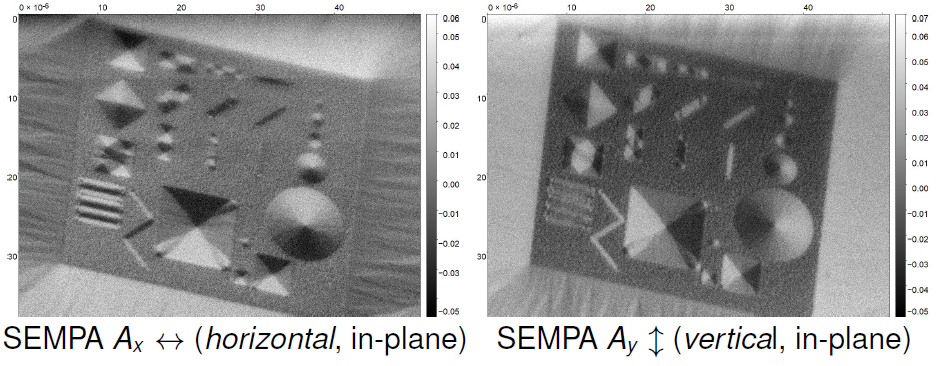
Fig. 1: SEMPA magnetic imaging of the sample. Two in-plane projections are shown (A stands for spin-asymmetry, quantity measured by the technique; it is directly proportional to magnetization). Acquisition (imaging) parameters
The sample is intended for testing and calibration (alignment) of Scanning Electron Microscopy with Polarization Analysis (SEMPA / spin-SEM). This is originaly ultra-high-vacuum-based microscopy technique featuring a detector that measures spins of electrons emitted from magnetic surfaces. Typically, these measurements enable the determination of two in-plane projections of magnetization with very high resolution—down to 10 nm (3 nm with special instrumentation). However, conventionally, such spin-resolved imaging works only for very clean sample surfaces.
Within the NCK2 (sub)project we explore possibilities to use such powerful microscopy under worse pressure conditions (poorer vacuum). This includes also sample surface modification (protection) - covering the surface with graphene as well as other approaches.
Since SEMPA measures two orthogonal magnetization projections (in-plane in this case), the sample contains structures with well-defined magnetization orientations. Some structures have magnetization only along 1 projection axis (magnetic contrast vanishes for the perpendicular projection - if instrument is well-aligned), other feature 4 domains having magnetization changing by 90° in between neighbouring domains.
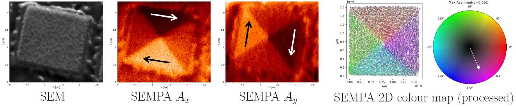
Fig. 2: As-obtained and processed images (2D colour map) of a Fe diesquare (edge 2 microns).